HOW DO SIM CARD WORKS ON MOBILE PHONES CIRCUIT
A SIM Card also known as Subscriber Identity Module, A SIM is a Smart Card that can store data from a cellular phone. Those data like identity, location and phone number, network authorization data, personal security keys, contact lists and stored text messages. Security features include authentication and encryption to protect data and prevent eavesdropping.
But how does this SIM card works within the mobile phones circuit? How does mobile phones reads and write data unto it?
In those particular questions above, If we learn answers unto it, we can solve problem issues regarding SIM related problems, like Insert Sim Card and etc.
Now here's a brief explanation on how does SIM Circuit Works on a mobile phones circuit.
A Sim Card have six pads that also corresponds to the six SIM connectors pins, but only five has totally have connection on the entire layout.
SIM DATA - this is a digital data that being stored on a SIM memory
SIM Clock - this is a clock frequency signal that being synchronize to the digital data to create data signal in order transfer or sends and receive data information.
SIM Reset - this is also a frequency signal that triggers or reset all synchronization process.
VSIM B+ Supply Voltage- This a power supply voltage used to activated the SIM circuit.
SIM Ground - a ground line voltage
The other one is not connected
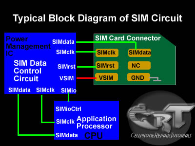
A Typical block Diagram above shows on how SIM Circuit Works on a Cellular phones circuits.
In the layout the Sim Interface Connector connected directly to SIM Control Circuit. The SIM Control Circuit is the one the generates Clock frequency that triggers the SIM data storage, once the SIM is now being triggered, it is then now sends data information to the application processor to begin the process with. The application processor is the one that gathered all data information from the SIM memory, initiate and activate it, if all information is in desired status.
Those three particular lines of signal flows associated in the circuit shows how the synchronization is being applied. If one of those lines being cut off the sending and receiving process will breakdown, and will result to SIM problem issues. The Power Supply Voltage through the SIM is also remain stable otherwise a lack of voltage will not activate the SIM to work.
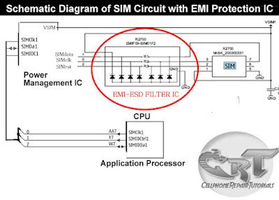
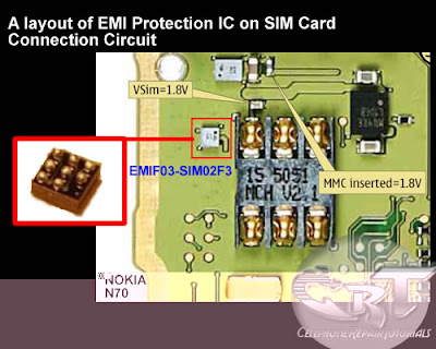
In a picture below an EMI-ESD Filter has been added to protect the circuit to an Electro-static Discharge and Electro-magnetic Interference disorders. This type of SIM connection circuit is an advantage to mobile phone technician for troubleshooting SIM related problem issues. Thus, type of particular EMI filter is very vulnerable and mostly create breakdown to the entire SIM connection.
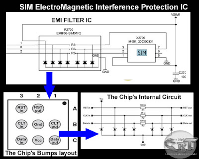
The picture below is an equivalent layout of an EMI filter and its internal circuitry,
only both frequency and data lines is being filtered.
The EMI Filter is a tiny chips designed to protect SIM DATA, SIM Clock and SIM Reset data signals that flow across trough the SIM connector.
The EMI-ESD Filter is a highly integrated device designed to suppress EMI(Electromagnetic Interference) and RFI(Radio frequency Interference in a circuit. This filter includes ESD protection circuitry which prevents damaging the mobile phone application when subject to ESD ( ElectroStatic Discharge) surges up to 15 kV.
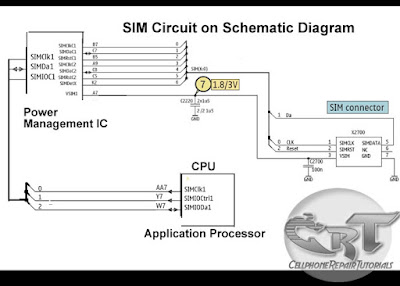
Here's an example of how the the SIM data signal flow across the printed circuit board.
Note: this is only shows where the signal flows from component to component connections.
A picture above is an alternative way by many mobile phone technician dealing with SIM problem issues on most Nokia Mobile Phones.
But how does this SIM card works within the mobile phones circuit? How does mobile phones reads and write data unto it?
In those particular questions above, If we learn answers unto it, we can solve problem issues regarding SIM related problems, like Insert Sim Card and etc.
Now here's a brief explanation on how does SIM Circuit Works on a mobile phones circuit.
A Sim Card have six pads that also corresponds to the six SIM connectors pins, but only five has totally have connection on the entire layout.
SIM DATA - this is a digital data that being stored on a SIM memory
SIM Clock - this is a clock frequency signal that being synchronize to the digital data to create data signal in order transfer or sends and receive data information.
SIM Reset - this is also a frequency signal that triggers or reset all synchronization process.
VSIM B+ Supply Voltage- This a power supply voltage used to activated the SIM circuit.
SIM Ground - a ground line voltage
The other one is not connected
A Typical block Diagram above shows on how SIM Circuit Works on a Cellular phones circuits.
In the layout the Sim Interface Connector connected directly to SIM Control Circuit. The SIM Control Circuit is the one the generates Clock frequency that triggers the SIM data storage, once the SIM is now being triggered, it is then now sends data information to the application processor to begin the process with. The application processor is the one that gathered all data information from the SIM memory, initiate and activate it, if all information is in desired status.
Those three particular lines of signal flows associated in the circuit shows how the synchronization is being applied. If one of those lines being cut off the sending and receiving process will breakdown, and will result to SIM problem issues. The Power Supply Voltage through the SIM is also remain stable otherwise a lack of voltage will not activate the SIM to work.
only both frequency and data lines is being filtered.
The EMI Filter is a tiny chips designed to protect SIM DATA, SIM Clock and SIM Reset data signals that flow across trough the SIM connector.
The EMI-ESD Filter is a highly integrated device designed to suppress EMI(Electromagnetic Interference) and RFI(Radio frequency Interference in a circuit. This filter includes ESD protection circuitry which prevents damaging the mobile phone application when subject to ESD ( ElectroStatic Discharge) surges up to 15 kV.
Here's an example of how the the SIM data signal flow across the printed circuit board.
Note: this is only shows where the signal flows from component to component connections.
A picture above is an alternative way by many mobile phone technician dealing with SIM problem issues on most Nokia Mobile Phones.


No comments:
Post a Comment